Page 1 of 1
27 Engine details
Posted: Thu Jul 09, 2020 12:36 pm
by Squirrel
Hi, I haven't played with Ts before a couple months ago...so I dove in, and took the car mostly all apart, fixed what I could find needed fixing, cleaned and painted, and put it back together. I'd like to get some input if I got it all together right (the stuff you can see, at least). Did I run the wires in the right place? Am I missing any parts? Are there any visible catastrophes in my future?
I will replace the radiator hoses, and the cracked carb body, when new parts arrive, other than that, I think it's all done.
Be picky, I want to learn...I'm not easily offended by facts

.
.
.
Re: 27 Engine details
Posted: Thu Jul 09, 2020 12:44 pm
by Mark Nunn
You installed cotter pins in engine pan bolts. There is no harm in doing that. The cotter pins were eliminated at some point but the castle nuts remained.
Is that picky enough for you?

Re: 27 Engine details
Posted: Thu Jul 09, 2020 12:47 pm
by Squirrel
That's excellent, thanks! I don't know this stuff, which is why I asked.
Were split lock washers used on the pan bolt nuts?
Re: 27 Engine details
Posted: Thu Jul 09, 2020 12:48 pm
by John Codman
Nice engine! I see that your '27 still has the vaporizer. The only thing that I see as incorrect is the harness from the timer to the coils. The harness runs across the front of the engine under the fan bracket. There is a clip (use 2 back to back) that holds the harness to the left side water outlet bolt, then the harness runs directly to the coils. There's nothing wrong with the way you did route the harness, but if you want to get really picky...
Re: 27 Engine details
Posted: Thu Jul 09, 2020 1:15 pm
by Squirrel
Thanks!
I redid the cable, I need to improve the clamp, but is this the correct routing?
.
.
.
Re: 27 Engine details
Posted: Thu Jul 09, 2020 1:20 pm
by John kuehn
Looks really good and you knew what you were doing.
Not that it makes a lot of difference but you used a flexible lower water hose on the bottom radiator outlet.
Ford used 2 short hoses and a steel pipe to make the length.
And no I don’t belong to the detail police!

But your a practical guy and used what you had in the shop which is exactly what folks would do when T’s were on the farm and in everyday common use.
But I do have to say the flex hose caught my eye! You asked. Looks good!
Re: 27 Engine details
Posted: Thu Jul 09, 2020 1:22 pm
by Squirrel
Thanks.
Actually the car came with those hoses. I am waiting for the correct ones (and metal tube) to show up in the mail any day now.
I never intended to get so picky about the details, but the replacement parts for these cars are really reasonably priced, and it's fun to do what I can to get it back to original.
Re: 27 Engine details
Posted: Thu Jul 09, 2020 1:23 pm
by CudaMan
Here's an older thread with diagrams showing the timer wire routing:
http://www.mtfca.com/discus/messages/17 ... 1315711433
Re: 27 Engine details
Posted: Thu Jul 09, 2020 1:44 pm
by Susanne
John kuehn wrote: ↑Thu Jul 09, 2020 1:20 pm
Not that it makes a lot of difference but you used a flexible lower water hose on the bottom radiator outlet.
Ford used 2 short hoses and a steel pipe to make the length.
The pipe was made of rolled and seamed flat sheet steel, painted black - I don't think there's a proper orientation for that seam - on it, the originals have the Ford logo stamped on it (as is almost everything on the car). I have one (1) good original one, I don't think it's ever been on a car... the rest I've had have rusted out... but of course, after sitting filled with water for a century shouldn't surprise anyone!
Now for my "confession" - I cheated on my car - I replaced the original steel (and leaking, right at the lower radiator hose) pipe with a length of copper pipe the same diameter... Originally painted it black, but 'round about 10 years ago I removed the black paint (and polished it), more trying to get a smidge more cooling out of it rather than for looks. Not sure if it helped or not, if I were pulling for points in a show, I'd paint it again. Factory original it isn't, but then again I don't think the factory intended our cars to still be on the road (and mechanically sound) 90-110 years after they rolled off the line. And "Angel" is (usually) a driver, not a garage queen...
I'm also not sure if they had switched from red rubber hose to black by 1927, I do know the earlier cars were red rubber... and those are available via the vendors. The original hose clamps were a different design, also.
You have an awesome car, and it's only going to get more and more fun as you go...
Re: 27 Engine details
Posted: Thu Jul 09, 2020 1:49 pm
by Squirrel
thanks, that means I have it pretty close now! The light wiring...I'm not sure about. The original radiator, which I got with the car, has a thin core, and has 3 tabs for holding wires along the lower tank. The replacement radiator that the PO installed is thick core, and has no place to run wires. I decided that running the wires over the front of the engine was the safest place for them.
.
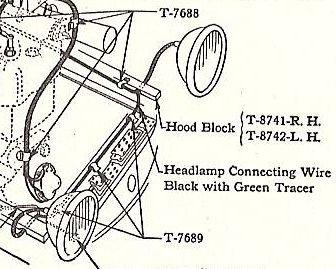
- wire routing.jpg (31.17 KiB) Viewed 10052 times
.
Re: 27 Engine details
Posted: Thu Jul 09, 2020 2:22 pm
by 2nighthawks
Sure looks good to me, but I would make one addition:
There's a little safety fuse holder kit you can get from any of the major parts vendors, and it's a really, REALLY good safety addition that's very inexpensive, easy to install, and good electrical insurance. The fuse (think it's 30amp but I'm not sure) is inserted in the main electrical power feed that comes off of the terminal where the starter cable attaches, and that one fuse protects the entire electrical system! It mounts right there on the starter next to the terminal post where the battery cable attaches to the starter,.....FWIW,.....harold
Re: 27 Engine details
Posted: Thu Jul 09, 2020 6:10 pm
by Squirrel
Thanks Harold, I have looked into those, and was thinking about adding it some time soon. I think I have the parts already, just need to make a mounting bracket,and wire it in.
Re: 27 Engine details
Posted: Thu Jul 09, 2020 6:38 pm
by George House
They call me ‘Style over Function’ around these parts.....but I feel your perfectly functional 4 manifold clamps are the early style. The New and Improved clamps are heavier duty and would install ‘flipped over’ from your style. Engine looks 600% better than my ‘27. Welcome !!!
Re: 27 Engine details
Posted: Thu Jul 09, 2020 7:05 pm
by Model T Mark
Should have domed nickel plated bolts on manifold clamps water inlet on head and block and valve cover to. I made mine out of stainless and buffed them.
Re: 27 Engine details
Posted: Thu Jul 09, 2020 7:27 pm
by Allan
George noted the manifold clamps. They are indeed the correct clamps but they are on backwards. On the 26-7 cars a shorter manifold stud with a shoulder was introduced, so the clamps were redesigned so they would go on either way and still be interchangable with early items. You need the shorter studs, if you are so inclined.
Allan from down under.
Re: 27 Engine details
Posted: Thu Jul 09, 2020 7:31 pm
by Squirrel
Thanks for the info on the bolts and studs. All of the head bolts but two appear to be the original domed head, as are the water outlet bolts. The nickel on almost all the parts on this car is long gone...I guess it wasn't very thick! When I feel like spending money, I might get some new bolts. But I also like using original parts as much as possible, so there's a trade off there, between looks and originality. The door handles, steering gear, lug nuts, hub caps, etc also need new nickel plating. The previous owner mentioned having the grill shell plated, and being disappointed that they chromed it instead of nickel plating it.
Re: 27 Engine details
Posted: Thu Jul 09, 2020 7:46 pm
by John kuehn
One more thing I noticed is the horn. Looks like it’s an ahooga horn. I had one almost like it.
Anyway it probably works pretty good.
The battery powered 6v horns from 17 (I think) to 27 looked alike except for the mounting bracket that was used on the 26-27 horns.
Your horn is period correct but not correct for a T. More than a few T’s have an AHOOGA horn that sounds like the name. T owners usually have a preference for the horn.
The Ford Model T horns make a WAAAANNK sound that lasts as long as you hold the horn button down!
To each their own as far as the sound goes!
Re: 27 Engine details
Posted: Thu Jul 09, 2020 9:00 pm
by Squirrel
You're right about the horn, it's a Klaxon 8C as best I can tell, probably from a Chevy from the mid 20s. I just got it on there and working. I made the mounting bracket, using part of the one that was on the horn, plus a piece of angle iron I had...the bracket is pretty well hidden, so you can't see how ugly it is
I like the sound. The horn came with the car, in a box with some other parts that didn't really fit.
Re: 27 Engine details
Posted: Fri Jul 10, 2020 8:52 am
by George House
By golly you’re right Allan ! Once I expanded the picture I saw they were the later heavier clamps. You’re right, all he needs are the 4 correct studs....
Re: 27 Engine details
Posted: Fri Jul 10, 2020 9:31 am
by DanTreace
Those later short studs with the shoulder appeared at the same time of those double duty clamps, that can be placed either way depending if the engine has the earlier long studs. The design change was late '24.
To be most correct for a '27, the manifolds used the new 3066C2, manifold stud with nickel head, these are actually dome headed bolts, and replace the stud completely.
Re: 27 Engine details
Posted: Fri Jul 10, 2020 9:58 am
by John Codman
John Kuehn mentioned the horn; my '27 came to me with an anemic but period correct AOOGA horn which soon died. I replaced it with a Fun Projects reproduction of the original. If I can ever find someone who will repair the AOOGA unit, (I think the armature needs to be rewound) I will reinstall it. The stock T horn sounds like the last gasp of a dying Cow.
Re: 27 Engine details
Posted: Fri Jul 10, 2020 11:13 am
by Squirrel
If I had a broken horn like that, I'd be tempted to fix it...another fun skill to learn!
Interesting about the manifold bolts/studs. My car has the original engine, and it had the Vaporizer on it when I got it. The throttle linkage all appears to be original. The studs had been in there a long time, and the nuts on a couple were stuck tight enough to the studs that I needed heat to get them loose. So...someone might have messed with it long ago, I don't know. I'll probably leave it for now, but at least now I know the correct bolts to get, thanks for all the help.
Re: 27 Engine details
Posted: Fri Jul 10, 2020 11:26 am
by Steve Jelf
If you want to correct the engine color, here's an original 1927 example.
Re: 27 Engine details
Posted: Fri Jul 10, 2020 12:35 pm
by Squirrel
I've seen the pics before of that engine...they didn't have any green like that at the hardware store, and I didn't feel like tinting the green I got with some black, to make it more drab. The wrong colors thing is something I'm ok with. I know that this car would need to be completely taken apart and redone to make it 100% right...I'm aiming for 85% on most of the stuff I do to it
Re: 27 Engine details
Posted: Fri Jul 10, 2020 1:27 pm
by TRDxB2
From an old discussion "The nearest proper color to what was is actually Ditzler 544, but you may not like it as it is more olive than green. "
http://www.mtfca.com/discus/messages/17 ... 1319580757
Color looks more like a semi-gloss olive drab. This is the same un-enhanced picture from the link and the one above in the discussion. Lighting gives a different look
Re: 27 Engine details
Posted: Fri Jul 10, 2020 7:01 pm
by Allan
The newish looking cut out on the generator looks like n A model item, having the output terminal screwed to the side of the unit. On most T's, there is a flat terminal protruding from the base of the cutout, and the wire is screwed to this terminal. Easily fixed later if you are so inclined. That is one very nice job by fellow new to model T''s. Well done.
Allan from down under.
Re: 27 Engine details
Posted: Fri Jul 10, 2020 7:21 pm
by Squirrel
Thanks! The cutout was on it already, it is an older Echlin part (from NAPA, I expect). One more thing to look for...
Re: 27 Engine details
Posted: Fri Jul 10, 2020 7:24 pm
by Joe Reid
It is not a Model A cutout, Model A’s are positive ground, Aftermarket diode cutout.
Re: 27 Engine details
Posted: Fri Jul 10, 2020 7:50 pm
by Squirrel
Joe Reid wrote: ↑Fri Jul 10, 2020 7:24 pm
Aftermarket diode cutout.
Are you sure?
.
.
.
Re: 27 Engine details
Posted: Sat Jul 11, 2020 1:18 am
by Allan
Jim, one can never be sure with model T's, on anything! State a fact and someone will have evidence/proof that the fact is wrong. It is the nature of the beast.
That said, the Echlin logo on your cutout cover is evidence that it is indeed an aftermarlet item. Most genuine Ford ones I have seen have the Ford script on the cover. You will notice that the output lead from the cutout is screwed to the side of the unit. That is the way it is usually done on A models. T model output leads are screwed down to a terminal which protrudes from the base of the cutout, similar to the generator end but with a full round threaded hole to take the screw. Others may be able to inform us if the A model type was introduced on late T production.
Allan from down under.
Re: 27 Engine details
Posted: Sat Jul 11, 2020 10:16 am
by Squirrel
It might be that the aftermarket parts companies decided to change the design, to one that would work on more than one application.
I was looking at cutouts a little bit, and there was a wide variety made...including rectangular shapes.
I expect I'll just keep the one I have, as long as it keeps working. I kind of like old, well made replacement parts, when I can find them. It's not 93 years old, but it's probably 50 years old.