Page 1 of 1
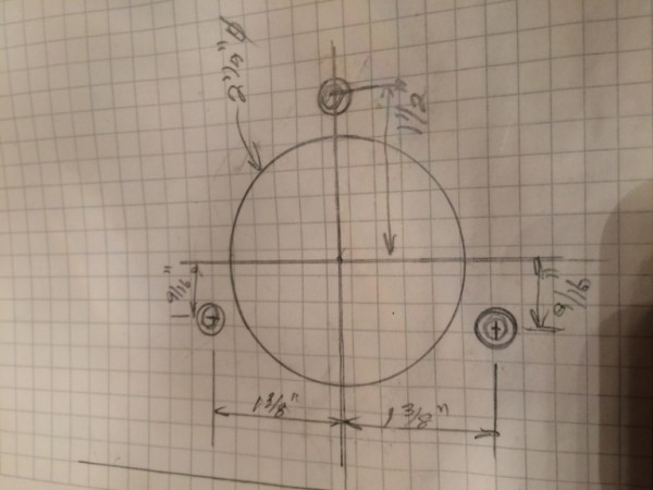
Generator bolt pattern drawing
Posted: Thu Jan 21, 2021 4:44 pm
by Les Schubert
Just wondering if someone has a drawing of this.
I am going to machine a adapter to fit in this place and if someone has already made the drawing it will save me some time as I can just go straight to my digital readout on my drill press.
Thank you for any help!!
Re: Generator bolt pattern drawing
Posted: Thu Jan 21, 2021 9:19 pm
by Les Schubert

- Got it solved
Re: Generator bolt pattern drawing
Posted: Fri Jan 22, 2021 1:35 pm
by Art M
The three bolts holes are on a bolt circle, but not evenly spaced. I will have to find my sketches from that project. I made a temporary block off plate.
Art Mirtes
Re: Generator bolt pattern drawing
Posted: Fri Jan 22, 2021 2:05 pm
by Les Schubert
I’ve played around with Henrys engine machining a lot and have realized that virtually every thing is located by 1/16” increments. A few exceptions (like the camshaft to crankshaft spacing)!!
Re: Generator bolt pattern drawing
Posted: Sat Jan 23, 2021 11:40 am
by Mark Gregush
When I was making my adapter plate, I found a lot of the measurements were 1/32 too.

Re: Generator bolt pattern drawing
Posted: Sun Jan 24, 2021 4:06 am
by ABoer
Les Sch .
The distance of the Camshaft and the Crankshaft is 100 m/m
Even the Bearings of the Generator are in m/m
Why did Henry That . ???
Take Care
Toon
Re: Generator bolt pattern drawing
Posted: Sun Jan 24, 2021 8:53 am
by Bill Robinson
As Les said:
100 mm = 3 15/16 ″
Re: Generator bolt pattern drawing
Posted: Sun Jan 24, 2021 12:21 pm
by Les Schubert
I have been promoting the 100 mm spacing for over 20 years. I figured it out when I found a very nice set of straight cut gears and realized that they weren’t a standard North American tooth, but were a perfect metric tooth profile spacing. So I made a 100 mm “link” for the line boring rig and no longer had any gear mesh issues. Before I ended up buying oversized cam gears half the time to get a decent mesh fit. The problem was that the “vertical” location of the camshaft tolerance was fairly “loose” and most line boring rigs located from the camshaft horizontally. Probably why I have never had a problem with fibre camshaft gears! The 3-15/16 spacing is.008” off. Not terrible but not great either.
To get back to my earlier comments, I had a opportunity to copy Fords factory block drawings and there I found that the bolt spacing were designed for 1/16” spacing. Your block will likely be off slightly as they had a manufacturing tolerance
Re: Generator bolt pattern drawing
Posted: Sun Jan 24, 2021 12:26 pm
by Les Schubert
Toon
My speculation is that using the metric gear profile was to make it more difficult for the “after market” manufacturers. It was no problem for Ford to make them to the spec. This is applicable to the straight cut early gears. When they went helical they just adjusted the fit.
Re: Generator bolt pattern drawing
Posted: Sun Jan 24, 2021 2:19 pm
by Dan McEachern
Yes, and pre 1926 Model T's use 762 x 88.9 mm tyres!
Re: Generator bolt pattern drawing
Posted: Mon Jan 25, 2021 3:43 pm
by Jerry VanOoteghem
Les Schubert wrote: ↑Sun Jan 24, 2021 12:26 pm
Toon
My speculation is that using the metric gear profile was to make it more difficult for the “after market” manufacturers. It was no problem for Ford to make them to the spec. This is applicable to the straight cut early gears. When they went helical they just adjusted the fit.
Are you saying that the timing gears are Module gears?
Re: Generator bolt pattern drawing
Posted: Mon Jan 25, 2021 4:49 pm
by Les Schubert
My observation is that the straight cut gears are “modular pitch”. I can’t comment on the helical gears.