Page 1 of 1
You got a lot of 'splainin' to do
Posted: Wed Sep 01, 2021 4:21 pm
by Steve Jelf
I'm asking those who understand simple electronics. Unfortunately that's an area where I suffer from serious MEGO. So I need help with this flasher wiring.
1 As this is a signal setup for a Model T and is meant to operate completely separately from the ignition system, should I skip Switch A and run the battery wire directly (through a fuse) to B?
2 What is the straight line A/D? I assume it's a wire, but I don't see how it's connected to anything.
3 I take Switch F (Turn Signal) to be a three position toggle with OFF in the middle position and Left and Right on either side. Is that right?
4 What is Switch C?
5 Am I right that this setup is completely separate from Brake and Tail Light circuits? That's OK. Those are so simple that even I understand therm.
If somebody can 'splain how all this works, maybe I can understand it. 
Re: You got a lot of 'splainin' to do
Posted: Wed Sep 01, 2021 5:31 pm
by Craig Leach
Hi Steve,
This wiring diagram is for a system with a emergency flasher that works with the ignition off. Thats the two switches above the T/S sw. yes a three possition switch off in the middle will work and this is seperate from the brake light. maybe this will help.
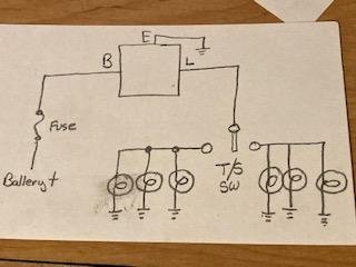
- EP34.jpg (12.17 KiB) Viewed 4786 times
Craig.
Re: You got a lot of 'splainin' to do
Posted: Wed Sep 01, 2021 8:12 pm
by TXGOAT2
(I guess ) A-D represents a mechanical link between 3 elements within the hazard warning switch. (?) Confusing to me.
Re: You got a lot of 'splainin' to do
Posted: Wed Sep 01, 2021 9:33 pm
by cslandry
Switches A, C, and D are parts of one three pole, two position switch. As mentioned, this gives you flashers when the ignition is off. If you dont want that function, you can eliminate that (those) switch(es) and run power to the flasher from the battery or the ignition switch.
Re: You got a lot of 'splainin' to do
Posted: Wed Sep 01, 2021 11:07 pm
by Steve Jelf
I got some advice by phone from a member who explained that the diagram I posted is badly done. What it seems to show as three switches should really be a single hazard switch with no connection among Source, Left, and Right when it's OFF, and Left and Right both connected to Source when it's on. Is that called a SPDT switch?
Even I can understand this. It makes sense to me.
Re: You got a lot of 'splainin' to do
Posted: Thu Sep 02, 2021 12:42 am
by MKossor
Steve,
The original schematic diagram you posted is fundamental correct. The horizontal line passing through switches A, C and D associated with the Hazard function should be a dashed line for better clarity showing those 3 switches are "ganged" to all switch in unison, NOT an electrical connection between those switches. Its a Triple Pole Double Throw (TPDT) switch.
The Hazard function is OFF as illustrated with all 3 switches in the left position. In other words, switches A, C and D are OPEN
The turn signal switch, F, is a Single Pole, Double Throw (SPDT) switch with Center Off function. The Ignition switch must be closed in order for the turn signal to operate. When the ignition switch is in the ON (closed) position, power is connected to the input of the blinker module. The turn signal switch can be moved from its center resting position to the left or right to activate the respective turn signal.
The Hazard function is activated by closing the hazard switch; all 3 switch elements move in unison and close together. Switch A provides power to the blinker module, switch C connects the blinker output (L) to the left signal lights and switch D connects the blinker output (L) to the right signal lights. in the hazard mode, the turn signal switch has no effect if it is switched from its normally center position to either left or right positions. There is no brake switch identified so presume that is a separate system. Hope this explanation helps with your understanding of how the blinker system works.
Regarding your simplified schematic; it appears the lower hazard switch terminal is connected to both left and right signal lights (electrically connecting them together) so when the hazard switch is open, the turn signal switch will activate all lights (ie hazard mode) if switched to either the left or right position. Thus, will ONLY function in hazard mode.
Brake light power isolation
Posted: Thu Sep 02, 2021 2:40 am
by Novice
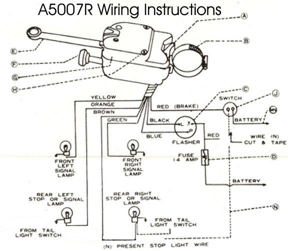
- directional diagram.png (258.38 KiB) Viewed 4483 times
I might add for clarification ? The tail lights and rear turn/stop lights have dual filament bulbs not shown in the circuit. the rear turn signal lights and stop lights use the same filament in each of the rear lights. The left tail light/license plate light and right tail light get their power from the tail light terminal on the ignition switch. the brake light power comes from the brake light switch. the circuit needs a blocking diode to keep to keep both left and right rear turn signals from coming on together at the same time and flashing when either left or right switch is activated since they are both tied together at the brake light switch.
The commercial turn signal switches have a separate wire for the brake lights and no external blocking diode is needed.
My 2 cents worth maybe less!
Re: You got a lot of 'splainin' to do
Posted: Thu Sep 02, 2021 8:28 am
by George Hand
Steve on you last diagram that has the hand drawn wire from the "Hazzard Switch" to the left side lamps I think you will need a pair of diodes to isolate the left & right sides George
Re: You got a lot of 'splainin' to do
Posted: Fri Sep 03, 2021 12:32 am
by Steve Jelf
...I think you will need a pair of diodes to isolate the left & right sides...
Not if both sides are disconnected when the switch is OFF.
Re: You got a lot of 'splainin' to do
Posted: Fri Sep 03, 2021 8:41 am
by George Hand
Steve, What i should have said is, Think the L & R lamps should be isolated by 2 isolation diodes from your jumper wire then the Hazard lamps can work with a simple SPST (on-off) & the Turn signals can work with a SPDT (on-off-on). I guess on your jumper wire I did not see how you isolated the L & R for turn signal operation (switch).
Re: You got a lot of 'splainin' to do
Posted: Fri Sep 03, 2021 8:57 am
by Rich Eagle
WOW!
This old curmudgeon still uses hand signals.
Using my left arm for safety.

I'm glad you young guys are figuring this out.
Rich
Re: You got a lot of 'splainin' to do
Posted: Fri Sep 03, 2021 10:03 am
by Steve Jelf
I do too, Rich. But as long as I'm modernizing my 1915 with visible taillights, I might as well go all the way with turn signals. These days there are people who don't know hand signals, and when they see you signal for a left turn they think you're waving them around. Could be a problem.
Re: You got a lot of 'splainin' to do
Posted: Fri Sep 03, 2021 10:39 am
by MKossor
So Steve, do you now understand the original schematic diagram function?
Perhaps I should have avoided the long winded explanation and stuck to providing direct, succinct answers to your questions; you did, afterall, ask for "lot of splainin" to do.
1 As this is a signal setup for a Model T and is meant to operate completely separately from the ignition system, should I skip Switch A and run the battery wire directly (through a fuse) to B? Ans: Yes, it operates separately from the ignition system. No, the diagram is fine as is; Hazard function works with key ON or OFF. Flashers only work when the ignition switch is ON.
2 What is the straight line A/D? I assume it's a wire, but I don't see how it's connected to anything. Ans: It means switches A, C, D are all "ganged" meaning they are all the same physical switch and switch in unison when toggled. The line AD should be dashed rather than solid to distinguish between electrical connection and the ganged relationship between switches.
3 I take Switch F (Turn Signal) to be a three position toggle with OFF in the middle position and Left and Right on either side. Is that right? Ans: Yes
4 What is Switch C? Ans: Switch C provides electrical connection between blinker module output and the left lamps when closed. Switch C is one of the switch elements part of ganged switch A, C and D. Switch D provides the same function for the right side lamps. Switch A provides electrical power to the blinker module input regardless of ignition switch position. The lamp side of switches C and D are electrically isolated when in the OFF position to permit normal operation of turn signals. (contrary to other comments, a Diode cannot be used to isolate left and right side lamps for the Hazard function to operate independently of the turn signal function, isolation using separate, ganged, switches is necessary)
5 Am I right that this setup is completely separate from Brake and Tail Light circuits? That's OK. Those are so simple that even I understand therm. Ans: Yes
Re: You got a lot of 'splainin' to do
Posted: Fri Sep 03, 2021 10:48 am
by Steve Jelf
Thanks to help here and offline, I think I've got this now.
Re: You got a lot of 'splainin' to do
Posted: Fri Sep 03, 2021 1:19 pm
by Novice
Steve. Are You texting while driving ? Thought You were on the way to OCF