Page 1 of 1
Adjusting buzzer coils
Posted: Thu Dec 16, 2021 11:47 am
by rainer
I have seen a very interesting device for adjusting buzzer coils, the ECCT tool.
Nice, but for my taste this is a little bit too pricy. I will not pay 400-500$ for such thing when I need it possibly 1 time a year.
So I will try to do it in "old way", by measuring the drawn current and setting it to approx 1.5 Amps. I also plan to build a little testing device by myself.
Is this process somewhere described in detail? Perhaps a wiring schematic if it is more than just applying DC voltage to the coil?
I wonder which voltage I should apply.
When running on BAT, the coil receives intermittent 6V voltage. But MAG gives much higher AC voltage of up to 23V or even more. So which voltage should I connect? 12V DC would be somewhere in the middle between BAT and MAG, so I tend to use 12V.
Measuring the capacitor is also relatively simple. I place a stripe of paper between the buzzer contacts (to keep then "open"), then I can use a simple capacitor tester connected to upper and lower contact (at the mounting bolts, of course). 0.47uF is big enough to be measured with every better multi-function multimeter.
But it would be helpful to know a reliable procedure. My coils are currently working fine, but this will allow me to test the device I build.
Re: Adjusting buzzer coils
Posted: Thu Dec 16, 2021 12:13 pm
by Norman Kling
I have a box with a gap for the spark and an ammeter to measure the current. I clean the points and set the gap first. Then I take an analog ohm meter and check for a movement one way or the other way to see if the capacitor is working. Then I place the coil in the box and adjust the tension till it draws 1.5 amps on the analog ammeter. I do this with the leads connectd to ground and the 6 volt connection on the terminal box. Then I start up the engine and switch to magneto. It should still draw 1.5 amps. If it does. I switch places with one of the coils in the car and if it runs fine the coil is a keeper. It is possible that that "expensive" tool can do a better job, but I take it out on a certain hill that I know with a run up to the hill I can climb all the way in high. If I have to shift down, then something is wrong. Either a fuel system or ignition system. If it pulled before I changed the coil and it pulls with the newly adjusted coil it is fine for my driving.
In order to do this, the engine must be warmed up and the same car with the same load must be used before and after.
Norm
Re: Adjusting buzzer coils
Posted: Thu Dec 16, 2021 12:18 pm
by Norman Kling
Were I said switch to magneto, I mean I move my wire to the magneto connection on the terminal strip. The engine can be running on battery while I do this, but the coil tester box should be connected to the magneto.
Norm
Re: Adjusting buzzer coils
Posted: Thu Dec 16, 2021 12:50 pm
by Chris Barker
All you questions are answered - many times over - on this recent thread~:
viewtopic.php?f=2&t=25606
'Setting up coils on the car'
The Strobospark is a somewhat cheaper simpler proven alternative to the ECCT.
It is a modern (and much lighter) development of Ford's HCCT.
You can get a Model T to run without the above, by setting gaps and current, but it will run much better with coils set up on one of the above - and the ECCT is probably the best. Or you can pay one of the reputable experts (who all use a proper tool).
Re: Adjusting buzzer coils
Posted: Thu Dec 16, 2021 1:42 pm
by Moxie26
You gentleman May complain about prices all you want.... Ford ignition coils are set by amperage not voltage, 1.3 amps is the ideal setting.
Re: Adjusting buzzer coils
Posted: Thu Dec 16, 2021 2:17 pm
by speedytinc
When running coils on magneto, they are not firing on AC voltage. They are firing on DC+ or DC- depending on which polarity passed the winding's.
A low voltage firing setting, say 4-4.5 volts, is low enough to spark the coils for the slow hand crank starting.
1.3 amps is the spec. I found that the coils set with an ECCT & rechecked showed an amp draw of 1.5-1.6 typically. FWIW
Re: Adjusting buzzer coils
Posted: Thu Dec 16, 2021 3:25 pm
by Art M
Use 3 D cell batteries and set the amperage at 1.3 with the buzz box. The spark should jump a .125 gap, which would be about 10,000 volts. The 10,000 volts is what old literature shows what is needed to start a model t.
The time to fire will not be accurate and the car wouldn't be as smooth as possible. But will probably be tolerable.
Adjusting dwell etc. is a whole other story. It takes money, skill, or equipment. Let us know your outcome.
There are those that claim an ECCT is the only way.
Art Mirtes
Re: Adjusting buzzer coils
Posted: Thu Dec 16, 2021 3:52 pm
by Kerry
John, what's converting the AC from the magneto to DC at the coil?
Re: Adjusting buzzer coils
Posted: Thu Dec 16, 2021 4:25 pm
by speedytinc
Kerry wrote: ↑Thu Dec 16, 2021 3:52 pm
John, what's converting the AC from the magneto to DC at the coil?
Its not converting, its using 1/2 of the AC cycle. When testing overall mag out put you are reading AC, but when the coils are firing they are only getting 1/2 cycle. Either + or -. Heres where the nodes come in. There is a peek (maximum) in the + or - voltage. Thats where you get max fire. That is THE spot for the timing lever. There are typically 4 optimal firing positions with your spark lever. @ those "nodes" the coils are seeing +,-,+,- current or -,+,-,+ depending on magnet orientation.
Re: Adjusting buzzer coils
Posted: Thu Dec 16, 2021 4:44 pm
by Been Here Before
Should you decide to build your own anti-ecct coil tester, and wish to set the coils with an AC voltage - as that produced by the vehicles magneto - make certain that the amperage meter is designed for AC. I will post later one that I made, and use a 22 volt AC laboratory power supply.
Re: Adjusting buzzer coils
Posted: Thu Dec 16, 2021 5:52 pm
by Poppie
Waiting for my other, as Scott_C noted (Two People, but I can now say Three and maybe Four are getting close) are on the right track of knowing the correct working and adjustment of the model T coil and magneto system....n
Re: Adjusting buzzer coils
Posted: Thu Dec 16, 2021 6:17 pm
by Scott_Conger
Neil
do the T world a favor and describe for everyone how the T ignition operates. For the betterment of humanity, this should not be kept among just you 3 or 4 folks.
Ron Patterson did a very nice job of it about 15 years ago and I'm curious as to how your understanding varies from that.
Re: Adjusting buzzer coils
Posted: Thu Dec 16, 2021 6:33 pm
by speedytinc
Scott_Conger wrote: ↑Thu Dec 16, 2021 6:17 pm
Neil
do the T world a favor and describe for everyone how the T ignition operates. For the betterment of humanity, this should not be kept among just you 3 or 4 folks.
Ron Patterson did a very nice job of it about 15 years ago and I'm curious as to how your understanding varies from that.
Ill second that. In search of full enlightenment.
Re: Adjusting buzzer coils
Posted: Thu Dec 16, 2021 10:00 pm
by Norman Kling
The points will actually last longer if you run on magneto, because with the current alternating in direction, your deposits go from one side to the other, while on battery they will always go from negative to positive leaving a little bit of metal on the opposite point. That is the reason they need to be filed or replaced from time to time. a good condenser will actually cause less sparking and the points will do better.
Norm
Re: Adjusting buzzer coils
Posted: Thu Dec 16, 2021 10:29 pm
by Kerry
So, we are back to the coils running on AC off the magneto and not DC unless it's running on battery, is that correct?
Re: Adjusting buzzer coils
Posted: Thu Dec 16, 2021 11:55 pm
by DHort
Rainer
I have a friend in Denmark who has a Strobospark. He may also have an ECCT., and he is able to respond on this forum. I do not know who else in Europe has the equipment to test your coils. Perhaps the gentleman in France or someone in the UK.
Re: Adjusting buzzer coils
Posted: Fri Dec 17, 2021 6:33 am
by rainer
speedytinc wrote: ↑Thu Dec 16, 2021 2:17 pm
When running coils on magneto, they are not firing on AC voltage. They are firing on DC+ or DC- depending on which polarity passed the winding's.
A low voltage firing setting, say 4-4.5 volts, is low enough to spark the coils for the slow hand crank starting.
1.3 amps is the spec. I found that the coils set with an ECCT & rechecked showed an amp draw of 1.5-1.6 typically. FWIW
Well, I didn't express well... Sorry for that.
I haven't measured yet, but does the drawn current change much between 6V and MAG voltage? If I understand right, the buzz coil should simply open the contact earlier when higher Voltage is applied, because the magnetic field increases quicker, so the average current drawn should be relatively constant then?
Re: Adjusting buzzer coils
Posted: Fri Dec 17, 2021 8:45 am
by speedytinc
Kerry wrote: ↑Thu Dec 16, 2021 10:29 pm
So, we are back to the coils running on AC off the magneto and not DC unless it's running on battery, is that correct?
Not the case. the coils are firing on a positive or negative leg of ac power, not a pulse of both. on magneto. If the timing is set to where its between the 2, + or -, it wont run well. The coil is receiving a positive or negative DC charge. Smarter folks than I describe whats going on better than I. MK & Ron Patterson.
Re: Adjusting buzzer coils
Posted: Fri Dec 17, 2021 10:23 am
by TXGOAT2
Assuming the timer is making contact, the coil primary isn't receiving any current unless the coil points are closed, whether the applied current is AC or DC. The points do not stay closed long enough for a complete alternating current cycle to occur at the speeds the Model T magneto operates at, thus the primary will receive either + or - current flow during the instant the points are closed when running on mag. (The coil's secondary winding output is always alternating current, since it is a resonate inductive device.) A steady DC current applied at the primary winding (points held closed) will result in no output from the secondary. The points are normally closed, and open very quickly when current is applied to the primary coil, whether that current source is AC or DC. Applying AC current at a high enough voltage and frequency to the coil primary would allow the coil to produce high voltage with the points held closed. I don't think the magneto on a T can reach a high enough AC voltage and frequency to allow the coil to fire the plugs directly. With the points held closed and AC current applied to the primary, it becomes a simple step up transformer, and the seconary voltage will be controlled by the input voltage and the turns ratio between the primary and the secondary coil. At high AC frequencies, things get more complicated, but that stuff is well beyond what would be encountered with the Model T magneto and iron core coil assembly.
Re: Adjusting buzzer coils
Posted: Fri Dec 17, 2021 11:08 am
by Jerry VanOoteghem
speedytinc wrote: ↑Thu Dec 16, 2021 4:25 pm
Kerry wrote: ↑Thu Dec 16, 2021 3:52 pm
John, what's converting the AC from the magneto to DC at the coil?
+,-,+,- current or -,+,-,+ depending on magnet orientation.
So, help me out here, isn't +-+-+-, etc... the very definition of AC current? How would the magneto output look in an oscilloscope trace? Like a sine wave? i.e. AC?
Re: Adjusting buzzer coils
Posted: Fri Dec 17, 2021 11:27 am
by TXGOAT2
It would appear as a sine wave, with the spacing of the peaks and null points getting closer together as the engine speed increases. Amplitude would also increase with engine speed. The effect would be to produce a "denser" flow of AC current, with higher amplitudes and more closely-spaced peaks and narrower (shorter) null points. If the engine speed got high enough, it might be possible for current to reverse polarity during the time the coil points were closed. I don't think the coil operation would be affected if it did, and I don't know if such a speed could be reached. As the amplitude of the mag output increased with speed, the points would be pulled open sooner, allowing less time for a polarity reversal to occur during the point closed period. As frequencies go up, coil windings begin to behave differently, and things get more complex. In the T system, you have the magneto frequency variations, the point dwell time and cycle frequency variations, inertia in the point assembly, and the coil primary and secondary have their own inductive characteristics that vary with frequency. The capacitor also has a charge time. Then ther'es the resisance across the plug gap, with varies considerabley during different engine operating modes. It's kind of like 20 hockey games going on at once on the same ice.
Re: Adjusting buzzer coils
Posted: Fri Dec 17, 2021 11:37 am
by speedytinc
Jerry VanOoteghem wrote: ↑Fri Dec 17, 2021 11:08 am
speedytinc wrote: ↑Thu Dec 16, 2021 4:25 pm
Kerry wrote: ↑Thu Dec 16, 2021 3:52 pm
John, what's converting the AC from the magneto to DC at the coil?
+,-,+,- current or -,+,-,+ depending on magnet orientation.
So, help me out here, isn't +-+-+-, etc... the very definition of AC current? How would the magneto output look in an oscilloscope trace? Like a sine wave? i.e. AC?
The 4 signs are the 4 node firing positions available with the advance lever. The coil is firing on 1 only, + or -. the coil is not firing on an AC cycle. As a magnet passes A winding, with the timer in position, it makes a positive or negative charge & fires.
Yes if watching total magneto output whall running, you see AC. A scope will show a wave. A bunch of AC power is not getting to the coil. Not like on battery, where a constant flow of electricity makes the coil buzz when the timer is making contact not running. On battery, when the timer makes contact, there is no wait for electricity to be generated, so instant fire. No nodes. Infinite range of advance.
Re: Adjusting buzzer coils
Posted: Fri Dec 17, 2021 12:04 pm
by jab35
Wow, this is getting 'interesting', and confusing. I'd suggest a re-read of Ron Patterson's most excellent article on this topic, that would save a lot of people a lot of typing. Happy Holidaze, everyone, respectfully, jb
Re: Adjusting buzzer coils
Posted: Fri Dec 17, 2021 12:21 pm
by Jerry VanOoteghem
speedytinc wrote: ↑Fri Dec 17, 2021 11:37 am
The 4 signs are the 4 node firing positions available with the advance lever. The coil is firing on 1 only, + or -. the coil is not firing on an AC cycle. As a magnet passes A winding, with the timer in position, it makes a positive or negative charge & fires.
Yes if watching total magneto output whall running, you see AC. A scope will show a wave. A bunch of AC power is not getting to the coil. Not like on battery, where a constant flow of electricity makes the coil buzz when the timer is making contact not running. On battery, when the timer makes contact, there is no wait for electricity to be generated, so instant fire. No nodes. Infinite range of advance.
Okay, so maybe let's not say that the coil isn't running on AC current, because that's what's in the wire, so to speak, but instead perhaps say that it fires during only a small segment of the AC wave form. The +/- or -/+ inflection points. Would you agree to that description?
As to, "A bunch of AC power is not getting to the coil." Well, it's all getting to the coil, so long as the timer contacts remain closed, but the coil is only firing during the inflections. If I recall, depending on the brand of timer, you may have 3 or 4 distinct opportunities for fire to occur during the duration governed by the timer. This goes back to my former reading of Ron Patterson's excellent article. Apologies if I "misremembered" anything in the intervening years.
Re: Adjusting buzzer coils
Posted: Fri Dec 17, 2021 12:50 pm
by speedytinc
Yes, your description of a small segment of AC fits.
During the duration of the timer, you get 1 firing. The next time a charge has been created(magnet passing a winding) making an opposite charged piece of a AC cycle, the timer is off or firing in a fired cylinder.
Ron Patterson's & mike Kossner's Descriptions are important in understanding & mastering the ignition system. MK's webnar is great. I mean to review RP's description soon.
I am but a humble student soaking it all in, trying to understand & optimize the systems performance.
After all, is it not "easier" to go dizzy Without the peculiarities & troubles? I love the challenge.
As a friend once said "Is it still a steak without the sizzle?"
Re: Adjusting buzzer coils
Posted: Fri Dec 17, 2021 2:39 pm
by MKossor
mike Kossner's Descriptions are important in understanding & mastering the ignition system.
Who?

How would the magneto output look in an oscilloscope trace? Like a sine wave? i.e. AC?
Nope, the magneto output waveform taken on my 1927 Touring looks like this:
 Viewed 4805 times")
The upper trace is the magneto output voltage (20V/div) applied to the coil and the lower trace is the coil current (2A/div). The voltage waveform is triangular. The spark lever is set such that the coil is operated on a single NEGATIVE magneto voltage pulse. Note how the voltage amplitude is attenuated as compared with the other magneto voltage pulses. This occurs due to the magneto internal resistance in which voltage is dropping as the coil current ramps up to ~6A when the coil points open and spark fires. Also note that there is a time between the Negative magneto voltage pulse when the coil current begins flowing. This time lag occurs due to the coil inductance property causing a phase shift between the magneto voltage and coil current. This time lag is the reason why the magneto coil ring is advanced (shifted) with respect to the crank shaft (piston TDC position). The amount of time lag changes with engine RPM so the amount of advance is a compromise for overall performance. The value was chosen of 7 degrees per Ron's excellent article on the Model T Ford Ignition System & Spark Timing.
Back to describing the waveform above: Spark fires when the lower trace coil current abruptly drops to 0A about 2ms after it began charging (Quiz question: does that TTF of 2ms ring any bells?) Note that there is no coil current or spark firing during the next positive magneto pulse; why is that? Because the coil points are still open from the 1st firing. The points close as the 2nd pulse (positive) is ending and the 3rd pulse (negative) is just beginning so the coil current only ramps up to ~2A and fires a weak spark of no consequence since combustion has already occurred. The timer roller/brush/flapper moves off contact and there are no more coil charging events for the remainder of magneto voltage pulses.
More information on how the Model T Ignition system works and the TTF method of adjusting coils covered here:
https://youtu.be/RYcGD-8Ol3s?t=357
Re: Adjusting buzzer coils
Posted: Fri Dec 17, 2021 5:00 pm
by TXGOAT2
That's a sawtooth wave, not a sine. I suppose that's due to the peculiarities of the T magneto construction.
Re: Adjusting buzzer coils
Posted: Fri Dec 17, 2021 8:25 pm
by MKossor
That's a sawtooth wave, not a sine.
Nope. Here are the differences between the various waveforms. Which one comes closest to the actual measured magneto waveform?
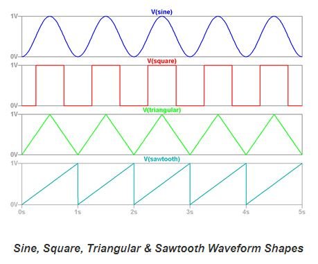
- Waveform Differences.JPG (34.17 KiB) Viewed 4727 times
The coil current waveform is actually a parabola (i=v^2) in response to the linear ramp of the magneto voltage change applied to the coil (inductor).
I suppose that's due to the peculiarities of the T magneto construction
Yep!
Re: Adjusting buzzer coils
Posted: Fri Dec 17, 2021 8:38 pm
by TXGOAT2
It's the Egyptian Wave!
Re: Adjusting buzzer coils
Posted: Fri Dec 17, 2021 10:45 pm
by Art M
Mr. Kosser,
Thanks for posting the oscilloscope display. If my interpolations, extrapolations, and arithmetic are correct, he dwell time is 2 millisecond and the crankshaft speed was about 1400 rpm, equivalent to 35 mph vehicles speed .
1. Is my analysis correct
2. If the dwell was set at 5 ms, wouldn't the coil output be compromised.
Art Mirtes
Re: Adjusting buzzer coils
Posted: Fri Dec 17, 2021 11:29 pm
by MKossor
Mr. Kosser
Who?
1. Is my analysis correct
Yep
2. If the dwell was set at 5 ms, wouldn't the coil output be compromised.
Yep
Just in case in the off chance this affirmation is not not already intuitively obvious to most casual observers, I offer the following for your consideration.
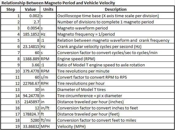
- Relationship between magneto frequency and vehicle speed.JPG (86.43 KiB) Viewed 4686 times