Page 1 of 1
Growler
Posted: Fri Mar 21, 2025 8:49 am
by SMH
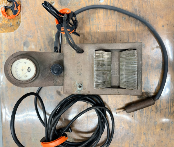
I am working to restore an Allen Electric E32 Growler. Does anyone have a wiring diagram/schematic they could provide a copy to make sure it is wired correctly? Or maybe take pictures of the wiring in a working E32?
Re: Growler
Posted: Fri Mar 21, 2025 9:15 am
by SMH

- Picture for reference
Re: Growler
Posted: Fri Mar 21, 2025 11:21 am
by jab35
Stephen: Some (most?) vintage growlers are wired with two wire non-polarized 120 VAC plugs. The continuity test for armature-commutator shorts on these growlers uses a resistor in series with a test probe along with a light or meter connected in series to one of the120VAC power leads. The other 120 V power lead is connected to the growler frame and metal case. With the armature on the growler bed you check for internal shorts by running the test probe along the commutator segments, a shorted segment 'lights' a light or moves a meter. Short story, the unit may be 'hot' if the plug is inserted in the outlet in a way that makes the plug wire to frame 'hot'. I've read posts on the forum where people 'upgraded' such units with 3-wire connections w/ground, accidently wiring the power cord plug with the hot lead and ground lead both going to the growler frame. Perhaps this is the basis of your question, others will know more about your specific Allen Growler. Growler is a great tool in my view, best to you. jb
You may be familiar with all this, but here's a vid of a similar unit being used in an armature test, cool stuff,
https://hackaday.com/2015/02/02/mike-sh ... e-growler/
Re: Growler
Posted: Sat Mar 22, 2025 10:02 am
by SMH
Thank you for the idea. Yes, my issue was when replacing the power cord, it seemed like a good idea to use the ground wire. Hooking the ground wire to the frame, caused a short when testing the commentator, I have removed the ground and now the test is successful.